The high-temperature ball valve generally adopts a metal hard sealing structure, and the ball and valve seat adopt hardening technology, including supersonic spraying, nickel-based spray welding, special surface hardening, cemented carbide spray welding, and high-impact, high-hardness ceramic materials or sintered tungsten carbide alloys. The surface hardness of the ball and valve seat can generally reach above HRC60, and the highest can reach above HRC74. The temperature resistance of the sealing surface material can reach 540℃, and the highest can reach 980℃; the bonding strength of the material can reach more than 10000 psi, and the sealing surface material also has good abrasion resistance and impact resistance.
The sealing of the valve seat and the valve body generally adopts graphite wire, and the butterfly spring is used to preload and absorb the blockage in the direction of the flow channel caused by high-temperature expansion. When the operating temperature exceeds 600℃ and the long-term operating temperature reaches 700 to 800℃, the sealing structure cannot meet the requirements for use. The graphite sealing ring is easy to oxidize and fail in a temperature exceeding 600℃, and the spring is easy to be used when the operating temperature exceeds 600℃. The valve stem is prone to elongation and make the sphere stuck at a high temperature above 600℃, resulting in a failure of opening and closing of the valve. The valve body and valve seat of the ultra-high temperature ball valve adopt a characteristic all-metal self-sealing structure, which can achieve the purpose of high-temperature elastic absorption of uneven expansion force in the direction of the flow channel. The special limit structure of the valve stem can prevent the valve stem from blocking the ball when it expands and stretches. The main seal in the flow channel is all metal, which avoids the sealing failure of the traditional graphite wire valve seat and the valve body caused by ultra-high temperatures. The lengthened valve stem and heat dissipation structure are adopted to ensure that the temperature of the valve stem packing is lower than 400℃, and the long-term effective operation of the packing is ensured. The special structure design of the anti-high temperature expansion making the ball not blocked by the extended valve stem can ensure the flexible operation of the valve at a temperature of 900℃. The purging of the middle cavity can prevent the blockage of the high-temperature slag, and the cooling system of the outer shell can prevent the material from running at an excessively high temperature for a long time, and ensure the high-temperature safety of the whole valve.
Design parameters
Media: High-temperature reaction boiler outlets
Medium temperatures: -29 to 900℃
Body Materials: 310S
Nominal diameters: DN100
Nominal pressure: 1.6 MPa
Connections: Flange ends
Drive modes: Worm gears
Installation positions: Top outlet and bottom discharge of large high-temperature reactors, long-term high temperatures of 800 °C
Structural features
The ultra-high temperature ball valve is mainly composed of the cooling part, the slag purge and anti-seize and the main valve. The structure of the ultra-high temperature ball valve is shown in Figure 1.
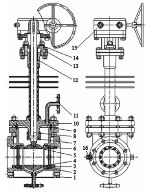
1. Valve bodies 2. Elastic sealing rings 3. Screws 4. Valve seats 5. Ball bodies 6. Adjusting screws 7. Limiting nuts 8. Valve stems 9. Sealing rings 10. Bonnets 11. Purge ports 12. Packing 13. Brackets 14. Packing glands 15. Worm gears 16. Cooling ports
Figure 1 The structure of ultra-high temperature ball valves
All-metal sealing structure of valve seats and valve bodies
Conventional high-temperature sealing structures use a combination of graphites and springs, but graphite is prone to high-temperature oxidation failure at 600°C, and springs are also prone to fail in an environment exceeding 600°C, failing to meet the requirements of design and use. In order to ensure that the valve can work normally under the high temperature of 800℃ for a long time and occasionally reaches 900℃, an all-metal sealing structure is adopted, and a special seal is designed, which can also play the role of a spring. Under the initial conditions, it can compensate the deformation and provide a certain sealing specific pressure. The structure of the seal is shown in Figure 2. The elastic seal is pushed by the adjusting screw, and the valve seat is fixed on the ball by the locking screw at a position of flexible opening and closing and suitable sealing pressure. At this time, the valve seat, the elastic seal and the hole in the valve body form a hard seal under the forced thrust of the adjusting screw, which can fully withstand the high temperature of 900℃. Under high temperatures, because of the uneven expansion, the sphere expands greatly due to heat, and the expansion is transmitted to the valve seat. The valve seat pushes the elastic seal, and the elastic seal is limited by the adjusting screw. At this time, since the elastic seal has a cantilever, the adjusting screw is pressed on the cantilever, and the cantilever is slightly bent, which effectively absorbs the uneven expansion of the sphere due to ultra-high temperature, and ensures that the valve is not blocked at high temperatures on the axis of the flow channel. The elastic seal is made of high-temperature resistant special material. There is an angular difference between the wedge angle of the seal, valve seat and the inner wall of the valve body, forming a line seal, which is convenient to form effective sealing pressure under the push of the adjusting screw. The part connecting to the valve body, valve seat and elastic seal should be hardened to effectively absorb the uneven expansion and deformation at high temperatures due to easy sliding, and also facilitate the elastic push of the valve seat after cooling down. Meanwhile, it can also ensure that the valve is effectively sealed under the alternating conditions of heating and cooling. The through hole on the elastic seal allows the locking screw to pass through to fix the valve seat in the sealing position at normal temperatures.
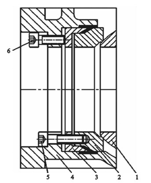
1. Balls 2. Valve seats 3. Elastomeric seals 4. Valve bodies 5. Locking screws 6. Adjusting screws
Figure 2 The structure of the sealing element
Special anti-high-temperature jamming structure between the stem and the ball
The anti-high-temperature blocking structure of the valve stem and the ball is shown in Figure 3. Since the valve is in an ultra-high temperature working condition, in order to prevent failures due to the high-temperature oxidation of the valve stem packing, an extension stem is adopted. However, because the valve stem is too long, the packing part stretches the valve stem toward the sphere due to the pressing force. The valve stem expands greatly at high temperatures due to the temperature rise, resulting in the sphere being stuck and not being unable to be opened and closed normally. Therefore, design a limit nut, screw the limit nut to the protrusion of the bonnet, and make the high-temperature elongation of the valve stem towards the packing and worm gear. The distance between the lower end of the limit nut and the sphere is very short, and the elongation of the valve stem is very small at high temperatures. By designing the gap E between the valve stem and the sphere, E is smaller than the elongation ΔL of the valve's limit operating temperature, effectively ensuring that it is not affected by the high temperature. The limit nut is also the limit component that effectively guarantees the gap E. The special limit nut structure effectively avoids the blocking of the valve in the axial direction of the valve stem, ensuring that it can be opened or closed flexibly and lightly under ultra-high temperatures.
The length thermal expansion of the metal is ΔL
ΔL=α·L(t2-t1 ) (1)
In the formula, α is the average thermal expansion coefficient (mm/mm·℃). L is the metal length (mm). t1 is the ambient air temperature (the temperature before heating up). t2 is the metal temperature (the temperature after heating up).
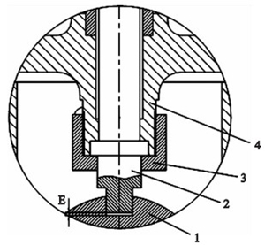
1. Balls 2. Valve stems 3. Limit sleeves 4. Valve stems
Figure 3 High-temperature anti-blocking structure between valve stems and balls
