The fully enclosed structure of
high temperature and high-pressure ball valves with zero leakage as well as selection methods and working principles of shielded electric devices are introduced in this article. The structural characteristics of the shielded control device of the
ball valve in a high temperature and high-pressure environment are analyzed. The design method of valve stems, valve seats and sealing structures of balls is given.
1.
Overview
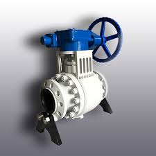
A ball valve is mainly used to cut off, distribute and change the direction of medium flow in the pipeline system. The opening and closing part of the ball valve is a sphere, which rotates 90° around the axis of the valve stem to achieve the purpose of opening and closing. A ball valve has the features of simple structures, small sizes, light weights and small installation space, which is one of valves with the fastest development in recent years.
The h
igh temperature and high-pressure ball valve with zero leakage is a new type of ball valve researched and manufactured in response to the existing problem of not being able to meet the requirements for high temperature and high-pressure conditions. Zero leakage of the ball valve under high temperature and high-pressure working conditions is realized.
2.
Structural characteristics
In the existing ball valve structure, flexible graphite packing is generally used for sealing between the valve stem and valve body or valve bonnet. Although the packing seal has the advantages of simple structure, low costs and wide applications, it also has the following disadvantages:
(1) The packing is in direct contact with the valve stem and is relatively rotated, which will cause wear of the valve stem and packing; leakage of the packing will occur after long-term use.
(2) The friction between the packing and valve stem causes the reduction of the effective power of the driving device. Partial power of the driving device is consumed by the friction between the valve stem and packing, resulting in useless power consumption of the driving device.
(3) Under high temperature and high-pressure working conditions, once the ball valve leaks, it may cause irreversible harm or injury. Therefore, the safety of the ball valve is very important under this working condition.
A fully enclosed structure is adopted for
high temperature and high-pressure ball valves with zero leakage; a shielded electric device is used to replace the original electric device. This electric device can be directly connected to the valve body and bear the pressure of the valve, so that packing is not required for the ball valve's stem and electric device, which can not only avoid external leakage, but also reduce the resistance of switching valves caused by packing, improving the external sealing and maintenance performance of the whole valve. The electric device and valve body are sealed with a stainless steel graphite wound gasket. This sealing structure has a wide range of application examples in high temperature and high-pressure conditions, and has been tested and verified in various working conditions, including damp and heat alternate working conditions and service life verification. It can meet the requirement for zero leakage.
3.
Structure composition
The high temperature and high-pressure ball valve consists of a shielded electric device and the ball valve itself. The shielded electric device is designed as an integrated structure with the shielded motor and gear reduction transmission mechanism, and the volume is much smaller than the traditional electric device. The ball valve itself is composed of a left valve body, a right valve body, a middle valve body, a ball, a valve seat, a sealing ring and a compensation spring. The structure of high temperature and high-pressure ball valves with zero leakage is shown in the Figure 1.
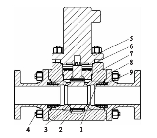
1. Seal rings 2. Thrust bearings 3. Balls 4. Left valve bodies 5. Shielded electric devices 6. Stainless steel graphite wound gaskets 7. Middle valve bodies 8. Right valve bodies 9. Compensation springs
Figure 1 High temperature and high-pressure ball valves with zero leakages
3.1
Shielded electric devices
The shielded electric control device is the actuator of the
high temperature and high-pressure ball valve with zero leakage, which not only provides power support for the opening and closing of the ball valve, but also is a component of the system pressure boundary. The shielded electric control device is mainly composed of a shielded motor, a shielding sleeve and a deceleration mechanism. The biggest difference between a shielded motor and an ordinary motor is that the rotor is placed in the shielding sleeve. The shielding sleeve forms an annular cavity to separate the stator and rotor of the shielded motor, and the decelerator is also installed inside the shielding sleeve. The output torque of the motor is directly output to the valve stem of the ball valve after the speed change of the reducer, so that the medium in the ball valve is isolated from the external mechanism of the shielding sleeve through the shielding sleeve, resulting in the valve stroke being in its fully enclosed structure.
3.2
Spheres
The upper stem of the ball valve sphere is integrated with the sphere and lower stem, and is processed as a whole. The upper end is directly connected to the output shaft of the electric device, so that the torque output by the electric device can directly act on the sphere, avoiding potential risks caused by excessive load-bearing parts. The ball and upper and lower valve stems have an integrated structure, which improves the overall strength of the rotating parts of the ball valve. The sealing surface of the ball and guide surface of the valve stem are processed only once by the precision sealing machining center, which ensures the accuracy of the sealing surface of the ball valve. The sealing surface of the sphere is welded with hard alloy, and the surface roughness Ra is less than or equal to 0.2μm after high-precision processing and grinding to ensure the sealing performance and service life of the inner sealing pair of the ball valve.
The upper valve stem of the ball is equipped with a positioning key, which cooperates with the positioning stop of the valve body to obtain the precise positioning of the circumferential position of the ball's switch valve. The upper and lower valve shafts of the sphere are installed on a pair of thrust bearings, and the sphere is accurately positioned through the lower positioning sleeve, thereby ensuring that the rotation center of the sphere and valve seat completely coincide, making sure the sealing performance and reducing the friction resistance. The fit clearance between the upper and lower valve stems and positioning sleeve has been calculated and checked, and the influence of thermal expansion and deformation has been taken into account, which not only ensures the positioning need for the sphere, but also makes sure the neutrality of the sphere relative to the valve seat, guaranteeing no jamming for the sphere in the rotation.
3.3
Valve seats
The valve seat adopts a floating structure with elastic compensation and pressure self-balancing functions. A spring energy storage sealing ring and a loading spring are arranged between the valve seat and valve body. The stiffness of the loading spring is accurately calculated to ensure that the valve seat meets the sealing requirements under any working condition. The spring energy storage ring is installed between the valve body and valve seat's shaft. After the ball valve is closed, the energy storage ring enters the pressure balance cavity through the gap between the valve seat and middle valve body; the pressure acts on the valve seat's shaft and pushes the valve seat toward the ball. At the same time, the medium outside the pressure balance cavity acts on the sealing center line of the valve seat and push it away from the sphere. The diameter of the valve seat's shaft and that of center lines of valve seat's sealing are calculated and checked in the process of design to ensure their diameters, improving the self-balancing performance of the valve seat.
The sealing surface of the valve seat is welded with hard alloys and the grinding is performed. At the same time, the effects of thermal expansion, motion wear and other factors are taken into account for the matching gap between the valve seat and valve body. The valve seat moves reasonably in the valve body's guide sleeve without any jamming, ensuring the automatic compensation performance of the valve seat under any working condition. (Figure 2).
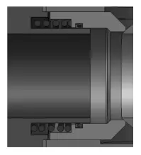
Figure 2 Valve seat's sealing structure with automatic compensation
The left, right and middle valve bodies are sealed with stainless steel graphite wound gaskets and pre-tightened by multiple bolts. The bolt pre-tightening force is calculated and checked to ensure the sealing performance of the left, right and middle valve bodies.
4.
Conclusion
Under high temperature and high-pressure conditions, the safety, sealing and reliability of the valve are strictly required. Factors such as strength, materials, processes and assembly of the valve should be fully considered in the design and manufacturing process. Understand and master the structure and sealing principle of high temperature and high-pressure ball valves with zero leakage to design and manufacture valve products with reliable performance, which is conducive to the wide use of high temperature and high-pressure ball valves with zero leakage under high temperature and high-pressure conditions, as well as overhaul and maintenance of such valves for maintenance support departments.
