Abstract: Aiming at the leakage often occurred during the manufacture and use of high-pressure three-piece ball valves, analyses and discussion are carried out from the three perspectives concerning the valve's structural characteristics, test methods and field use, and solutions are proposed.
1. Overview
In the hydrotreating process of the refining unit, the valves used are all high-pressure metal seated ball valves of large diameter. High-pressure ball valves are all made by forging considering the particularity of the working conditions, the R&D and manufacturing processes being highly difficult, safe operation of devices and casting are rarely adopted. At the same time, the cost is taken into account. Most high-pressure metal seated ball valves adopt a three-piece structure, and the pressure testing method of the top cylinder press with high working efficiency is used for the pressure test. However, the leakage of the flange often occurs during the manufacturing and operation process, which has a great impact on the reliable production of the product as well as safe and stable operation of the device.
2. The analysis of the problem
Because the test pressure is high, the jaws of the press cannot withstand the high test pressure; there is limited valve space and the jaws cannot be inserted into the end flange, so it is rarely used in the test of high-pressure ball valves. In the pressure test, two typical testing methods are often used, namely the top cylinder press and the blind plate pressure test. (Figure 1)
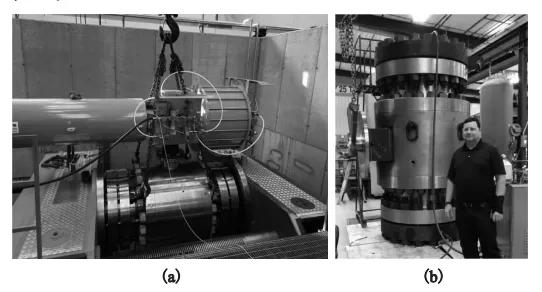
Figure 1 Typical pressure test methods for ball valves
The top cylinder press has the characteristics of high working efficiency and flexible operation, which is widely used at home and abroad. Its working principle is to apply axial thrust to the two ends of valves to hold the valve tightly, and the thrust of the top cylinder is often applied based on the experience of the operator; there is no certain rule, which will have a certain impact on sealing of the flange or even damage to it.
In the machining process, the inner hole of the forged two-piece valve body is a small hole that is smaller than the diameter of the end flow channel and has a machining allowance. It is not a type with a big body and a small flow channel. The processing amount of the internal cavity is much, and the processing cost is high. Therefore, a three-piece valve body structure is usually adopted in production considering the processing cost. When the three-piece structure is adopted, if the flanges of the left and right valve bodies meet the strength requirements, the length left for the middle body is relatively short due to the fixed length of the valve structure. There will often be insufficient space for the valve stem, and the threaded holes of the left and right valve bodies will cause interference problems. In the process of manufacturing, the method of reducing the thickness of the flanges in the left and right valve bodies is often used to increase the space of the valve stem in the middle body. Therefore, the thickness of the middle flange is reduced.
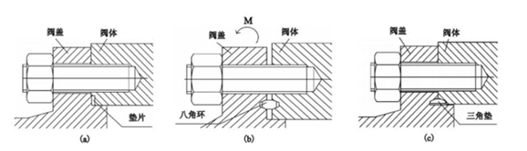
Figure 2 Typical sealing of flanges
(a) Spiral wound gaskets (b) Octagonal gaskets (c) Triangle gaskets
In the test, it was found that when the flange with a spiral wound gasket sealing structure is adopted (Figure 2a); the top cylinder type compress can assist with the sealing of the middle flange. It did not leak for the first test. After the axial force is not applied, the screws of middle flanges will loosen; the flange will leak when tested again.
When the middle flange has an octagonal gasket sealing structure (Figure 2b), there is a gap between the valve body and valve bonnet. Under the action of the axial force of the top cylinder, the octagonal gasket restricts the displacement. The thickness of the middle flange is thinner. In this case, the middle flange will be warped and deformed, which will cause the middle flange to leak when the top cylinder test press is used for the pressure test. In the entire test process, bolts of middle flanges do not bear the axial tensile force generated by the internal pressure of the shell, so it is impossible to test whether the strength of the middle flange's studs meets the pressure requirements.
